Model checking exactly-once
by Tomek Masternak, Szymon PobiegaDesigning distributed algorithms is a challenging task. It’s not that hard to reason about “happy paths” and show that at least sometimes the algorithm does what we intended. Checking that it always behaves as expected is a completely different story.
By definition, any non-trivial distributed system is concurrent and fails partially. Both elements adding up to the combinatorial explosion of possible executions - too many to fit in a single person’s head or analyze by hand. Fortunately, there are well-established verification methods we can use to do more rigorous testing.
Welcome to TLA+
If there’s one person to know in Distributed Systems research it’s Mr. Leslie Lamport. He’s a father to many discoveries and inventions in this area, including formal verification techniques. Since 1999 he’s been working on TLA+ - a specification language, and TLC - a checker for validating claims about models expressed in the language1.
In this post, we are not going to introduce you to TLA+ but rather provide some intuition and context needed to understand how we used it to validate exactly-once algorithms. If you are new to the subject we encourage you to have a closer look. There are several resources available on-line2 that do an awesome job at teaching TLA+.
Modelling systems with TLA+
TLA+ is a specification language for describing digital systems. A model of a system expressed in TLA+ consists of two elements: an initial state, and a next-state relation. The relation links a state to a set of possible next states. The fact that there might be several possible next states enables expressing nondeterministic behaviors caused by concurrent processing and partial failures.
Applying the next-state relation on the initial and the following states generates all possible system executions - sequences of state transitions the system can take. Such a model is a directed graph where nodes are states and there is an edge from state A to state B if B belongs to the next states set of A. Any possible execution of the system is some path in that graph. Validating the model is checking that some properties are true for all the paths.
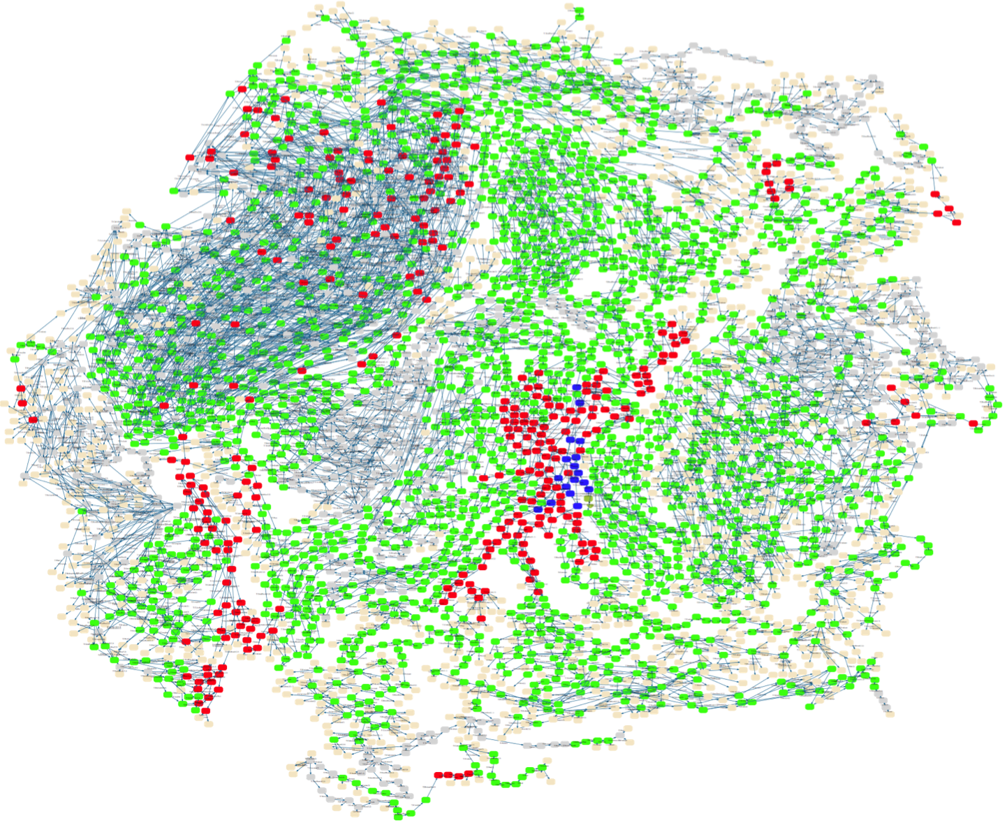
CAN bus protocol model visualization.
https://www3.hhu.de/stups/prob/index.php/File:CANBus_sfdp.png
The first step in using TLA+ is to create a model of the system. By definition, a model is a simplification, in our concrete case, a reduction necessary to make the verification feasible. We need to express only the essential parts of our system, otherwise, the state space size (number of unique system states) will be too big for the checker to handle. As with any modeling activity figuring out what are the important parts is the tricky bit.
We already touched on the subject in the introduction saying that distributed systems are mainly about concurrency and partial failures. Our goal is to verify that the system behaves as expected in the face of this reality. As a result, nondeterminism caused by concurrency and possible failures are the key elements that should make it to the model.
Finally, a note of caution. To create a useful model one needs a thorough understanding of the system. It requires a good understanding of the communication middleware, storage systems, libraries, etc. to properly express their concurrency and failure characteristics. It might be tempting to start with the model but based on our experience we wouldn’t recommend this route3.
Modelling exactly-once
We are not going to look at the specification line-by-line - we encourage all the readers to have a look at the source code for the complete picture. We used PlusCal to create the model - a Pascal-like language that gets transpiled to TLA+ by the toolbox. We think PlusCal makes it easier to understand the logic of the algorithm - especially for the newcomers.
The specification models a system with the following attributes:
- Business datastore supports optimistic concurrency control on writes
- There are no atomic writes between outbox storage and business datastore
- Message is picked from the queue and processed concurrently by the handlers
- Logical messages are duplicated
- We assume linearizabile consistency model for outbox and datastore4
The main goal of the specification is to enable model checking that the system behaves in an exactly-once way.
Scafolding
We will start with the scaffold for the specification, modeling input and output queues, business data storage, and message handlers.
 1CONSTANTS MessageCount, DupCount, NULL
 2
 3IsEmpty(T) == Cardinality(T) = 0
 4
 5Processes == 1..2
 6MessageIds == 1..MessageCount
 7DupIds == 1..DupCount
 8VersionIds == 0..2*MessageCount
 9TxIdx == 1..MessageCount*DupCount
10
11(*--algorithm exactly-once
12variables
13    inputQueue = [id : MessageIds, dupId : DupIds],
14    store = [history |-> <<>>, ver |-> 0, tx |-> NULL],
15    outbox = [r \in MessageIds |-> NULL],
16    outboxStagging = [t \in TxIdx |-> NULL],
17    output = { },
18    processed = { }
19(...)
20fair process HandlerThread \in Processes
21variables
22    txId,
23    msg,
24    state,
25    nextState
26begin
27MainLoop:
28    while TRUE do
29    LockInMsg:
30        await ~ IsEmpty(inputQueue);
31        (...)
32    end while;
33end process;
34end algorithm; *)
The model describes the state using a set of variables (lines 13-18). Input and output queues are modeled with sets (no ordering) with each message having a unique id and dupId unique for each duplicate. The business data storage (line 14) is a record that holds a sequence of snapshots (all versions of the state including the newest), ver field used to model optimistic concurrency on writes, and tx field needed by the algorithm to commit message processing transactions. Finally, there are two variables modeling the outbox store.
The system starts with all an empty state except the input queue which contains MessageCount*DupCount messages. There are two handlers (this is controlled by the Processes sequence) that operate in a loop (line 27) processing one message at a time.
The specification already expresses some non-determinisms as there is no coordination between the handlers. E.g. an execution in which the first handler processes all the messages as well as one in which it processes none of the messages both belong to the model.
Termination
Before checking any other poperties it’s good to make sure that the system doesn’t get stuck in any of the executions. In our case, proper termination means that there are no more messages in the input queue and both handler are waiting in LockInMsg. This can be expressed in TLA+ with:
1Termination == <>(/\ \A self \in Processes: pc[self] = "LockInMsg"
2                  /\ IsEmpty(inputQueue))
The property states that eventually (<> operator) any execution leads to a state in which the inputQueue is empty and all processes are in LockInMsg label.
Message processing
Now let’s look at message processing logic:
 1if outbox[msg.id] = NULL then
 2   txId := (msg.id-1)*DupCount + msg.dupId;
 3   state.tx := txId ||
 4   state.history := <<[msgId |-> msg.id, ver |-> state.ver + 1]>>
 5                    \o
 6                    state.history ||
 7   state.ver := state.ver + 1;
 8StageOutbox:
 9   outboxStagging[txId] := [msgId |-> msg.id, ver |-> state.ver];
10StateCommit:
11   CommitState(state);
12OutboxCommit:
13   CommitOutbox(txId);
14StateCleanup:
15   CleanupState(state);
16end if;
First, we check if the outbox contains a record for the current message. If there is not track of the message we generate a unique txId for this concrete execution (line 2) and run the business logic. The business logic execution is modeled by capturing msgId and state.ver in snapshot history. Please note that these operations are modeling in-memory hander state changes - state is a variable defined locally.
Next, we stage the outbox records, commit the state, and apply the side effects. All this modelled as 4 separate steps using StageOutbox, StateCommit, OutboxCommit, and CleanupState labels. Separate steps model concurrency but more interestingly, together with failures model the lack of atomic writes between outbox and business data stores.
Failures
Failures are the crux of the model and there are many that can happen in the system. We already made sure that the model expresses the atomicity guarantees of the storage engines. Now we need to make sure that write failures are properly represented. This has been done inside dedicated macros - one for each storage operation. Let’s look into one of them:
 1macro CommitState(state) begin
 2    if store.ver + 1 = state.ver then
 3        either
 4            store := state;
 5        or
 6            Fail();
 7        end either;
 8    else
 9        Fail();
10    end if;
11end macro;
As we can see we start with modeling the concurrency control check on the business store. What is more interesting though, we use either-or construct to specify that a write operation can either succeed or fail (for whatever reason). This causes a model checker to create a “fork” in the execution history. One following the happy path and the other representing write failure. The Fail macro brings the handler back to the beginning of the loop - as if an exception has been thrown and caught at the topmost level.
The other classes of failures are these which happen at the boundary between queues and the handlers. There are quite a few bad things that can happen in there:
- The message lease can expire and the message can be processed concurrently - either by a different thread or different process
- There can be communication failure between the queue and the handler resulting in the message being processed more than once
- There can be duplicates of a logical message generated on the sending end
- Handler can fail before ack’ing the message that will cause message reprocessing
- Message processing can fail multiple times resulting in message moving to the poison queue
Fortunately, from the handler perspective, all the above can be modeled with a single failure mode ie. logical message being received more than once. This has been modeled with the dupId field on the input message that we already talked about.
Checking safety
With all the pieces in place, we are ready to talk about the safety properties we want to check. This is how we defined exactly-once property in the consistent messaging post:
(…) we want an endpoint to produce observable side-effects equivalent to some execution in which each logical message gets processed exactly-once. Equivalent meaning that it’s indistinguishable from the perspective of any other endpoint.
Similarily to termination we can express that as TLA+ property:
 1AtMostOneStateChange ==
 2 \A id \in MessageIds :
 3    Cardinality(WithId(Range(store.history),id)) <= 1
 4
 5AtMostOneOutputMsg ==
 6 \A id \in MessageIds :
 7    Cardinality(WithId(output, id)) <= 1
 8
 9ConsistentStateAndOutput ==
10 LET InState(id)  ==
11        CHOOSE x \in WithId(Range(store.history), id) : TRUE
12     InOutput(id) ==
13        CHOOSE x \in WithId(output, id) : TRUE
14 IN \A m \in processed:
15     InState(m.id).ver = InOutput(m.id).ver
16
17Safety == /\ AtMostOneStateChange
18          /\ AtMostOneOutputMsg
19          /\ ConsistentStateAndOutput
This time the property is a bit more complicated - it consists of three parts that all need to be true (/\ is a notation for logical and)
AtMostOneStateChangestates that for any messageidin the input queue there can be at most one state change committed associated with that messagesAtMostOneOutputMsgstates that there can at most one output message for any unique input messagesConsistentStateAndOutputstates that for any fully processed input message (a message that ended-up in theprocessedset) the output message has been generated based on the business state version that got committed
Summary
We hope that you gained some intuition about model checking and how valuable this technique can be. That said, it’s worth stressing some points:
- You need to have in-depth knowledge about the technology to build a useful model. Otherwise, you are very likely to miss some key attributes of the system.
- Model checking doesn’t prove anything. First, it’s not proof in the mathematical sense, secondly, it’s always a simplification, not the system itself.
- Model sizes ie. numbers of states, used in practice are small. In our case, this was 2 handlers and 6 messages in the input queue. That said are is some empirical evidence that even small are good enough to find bugs.
- Model checking is yet another testing technique - arguably quite useful in the context of Distributed Systems
There are other bits of the specification that we did not discuss here. E.g. what are the non-trivial details needed to make the algorithm safe, how to make the model finite … and many more.
If there is any specific part that interests you, don’t hesitate and reach out on Twitter!
-
There’s more that comes with the toolkit eg. IDE and TLAPS - a theorem prover developed by Microsoft Research and INRIA Joint Centre ↩︎
-
TLA+ Video Course and Specifying Systems by Leslie Lamport. Learn TLA+ tutorial and Practical TLA+ by Hillel Wayne. Murat Demirbas and Marc Brooker also have some great content on the subject. ↩︎
-
Please note that we are talking about validating production systems rather than distributed algorithms. ↩︎
-
See Linearizability. ↩︎